
|
|
| ||||||||||||||||||||||||
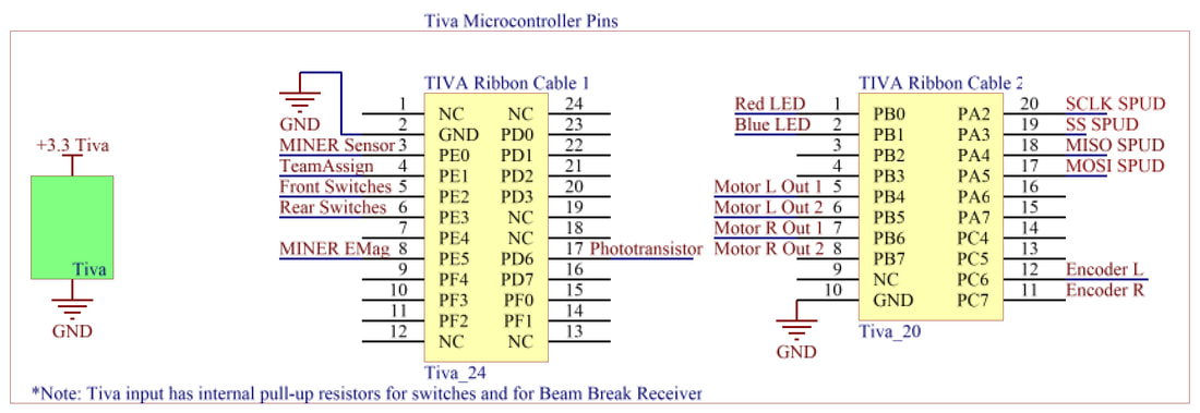
TIVA Pins
The TIVA microcontroller allowed us to receive input from our sensors and to send commands to our motors, SPI communication devices, and electromagnet. We used 4 PWM pins to control our motors, supplied power to our SPUD and team switch, engaged an input capture interrupt for our encoder ticks and MINER detection circuit, communicated with our SPUD using SPI communication protocols, and periodic interrupts to implement PI control of our motors.
MINER Detection Circuit
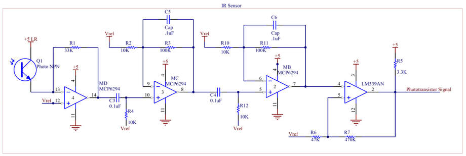
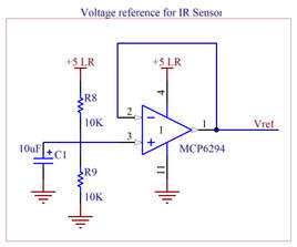
The detection circuit’s purpose is to take an analog signal from the phototransistor and amplify it before outputting it as a digital signal. This is achieved through signal conditioning, AC coupling, amplification, and hysteresis. One section of the circuit creates a voltage reference that helps us get a linear response and is later used throughout the different stages of the detection circuit. In contrast to our earlier usages of this circuit in this class, we added another gain stage here to increase amplification and better overall MINER detection. Our TIVA pin that receives the signal uses an input capture interrupt to detect the edges of the signal and identify if we have locked our sights on a MINER.
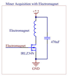
MINER AcquisitionIn our MINER acquisition circuit, we replaced the electromagnet that was given to us (2.5 kg) with a 25 kg electromagnet, so that we would better be able to hold and move the MINER. We set up our circuit using a power MOSFET that could be controlled by the TIVA and adding a capacitor across the power rails to suppress high frequency noise.
|
|
|
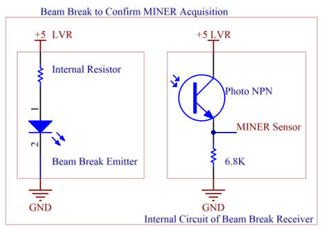
MINER Presence SensingOur beam break was placed across our plow, so that when a MINER entered the area, we could use the breaking signal as a cue to activate our electromagnet and grab the MINER. The LED side of the beam break was connected to a current-limiting resistor and powered by a linear voltage regulator. The phototransistor side had a signal wire going to the TIVA and an internal circuit that made the output digital in nature.
|
|
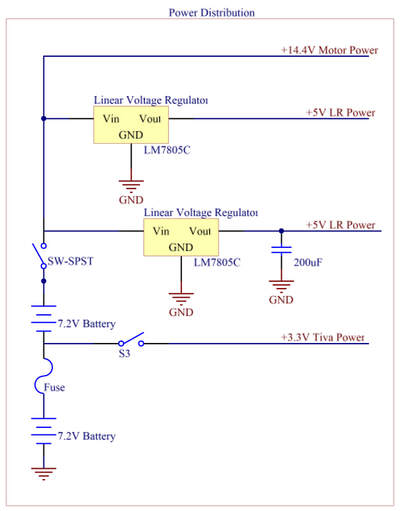
Power DistributionOur power distribution board utilizes both batteries to source current to the TIVA, the motors, and our other circuits. It also allows for easy switching off of the motors and of the TIVA, so power could be conserved during testing and we could ensure the safety of everyone interacting with the robot. The PDB is configured as part of a terminal block, so that common ground is easily maintained and our diverse set of components receive the power they need. The phototransistor MINER detection circuit runs off of its own 5V linear voltage regulator. The other LVR is used for our other circuits that required 5V. The TIVA is powered off of one battery and the motors are powered off of two batteries. Our 5A fuse protects the circuit against a surge in current.
|
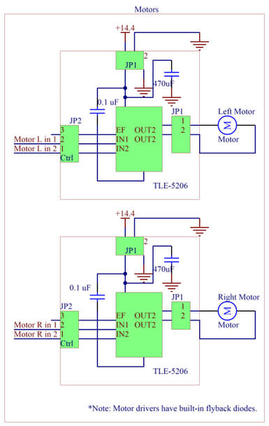
Drive MotorsOur motors were driven by two TLE-5206 motor drivers that had embedded flyback diodes to reduce voltage spikes due to the inductive load turning off. The drivers enabled us to send PWM signals to the motors and rotate them forward or reverse depending on the needs that we had during the game.
|
|
|
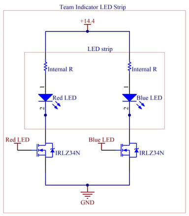
Team IndicationOur robot needed to indicate which team it was on, so we chose to use an RBG LED strip to show if we were on blue or red. We used two power MOSFETs to control the signals of the LEDs in a low side drive configuration.
|
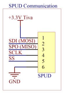
SPUD CommunicationTo figure out the MINER’s location, the scoring locations, and the score of the game we used a SPUD that was given to us by the lab and used SPI communication protocols to parse information and react accordingly. The SPUD was powered off of the TIVA and its data lines were wired to the TIVA, so SPI communications were possible. We read from all 11 registers on the SPUD to get game-critical information.
|
|
|
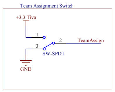
Team AssignmentOur team assignment switch allowed us to quickly switch teams before the game began and light up the appropriate LEDs based on the switch’s location.
|
